ESP32-C3-WROOM-02
WROOM module · based on ESP32-C3 · Active
- RISC-V
- 1× @ 160 MHz
- Wi-Fi 4
- BLE 5.x
- 4 / 8 / 16 MB flash
- 15 GPIO
- PCB antenna
As an affiliate we may earn from qualifying purchases. Prices and availability are set by AliExpress.
Interactive 3D model · drag to rotate
Every figure here is checked against Espressif’s official datasheets. We’ve taken every care to keep it accurate — but datasheets are dense and mistakes happen, so if something looks off, please report it.
The ESP32-C3-WROOM-02 is a general-purpose Espressif module built on the ESP32-C3 single-core RISC-V SoC clocked up to 160 MHz. It pairs 2.4 GHz Wi-Fi 4 and Bluetooth LE with up to 16 MB flash, routes the radio to a PCB antenna, and breaks out 15 GPIO; the module measures 18 × 20 × 3.2 mm.
It's a balanced Wi-Fi + Bluetooth LE module suitable for a wide range of connected products. Secure boot and flash encryption are available for production security. Espressif lists target uses including Smart Home, POS Machines, Industrial Automation, Service Robot and Health Care.
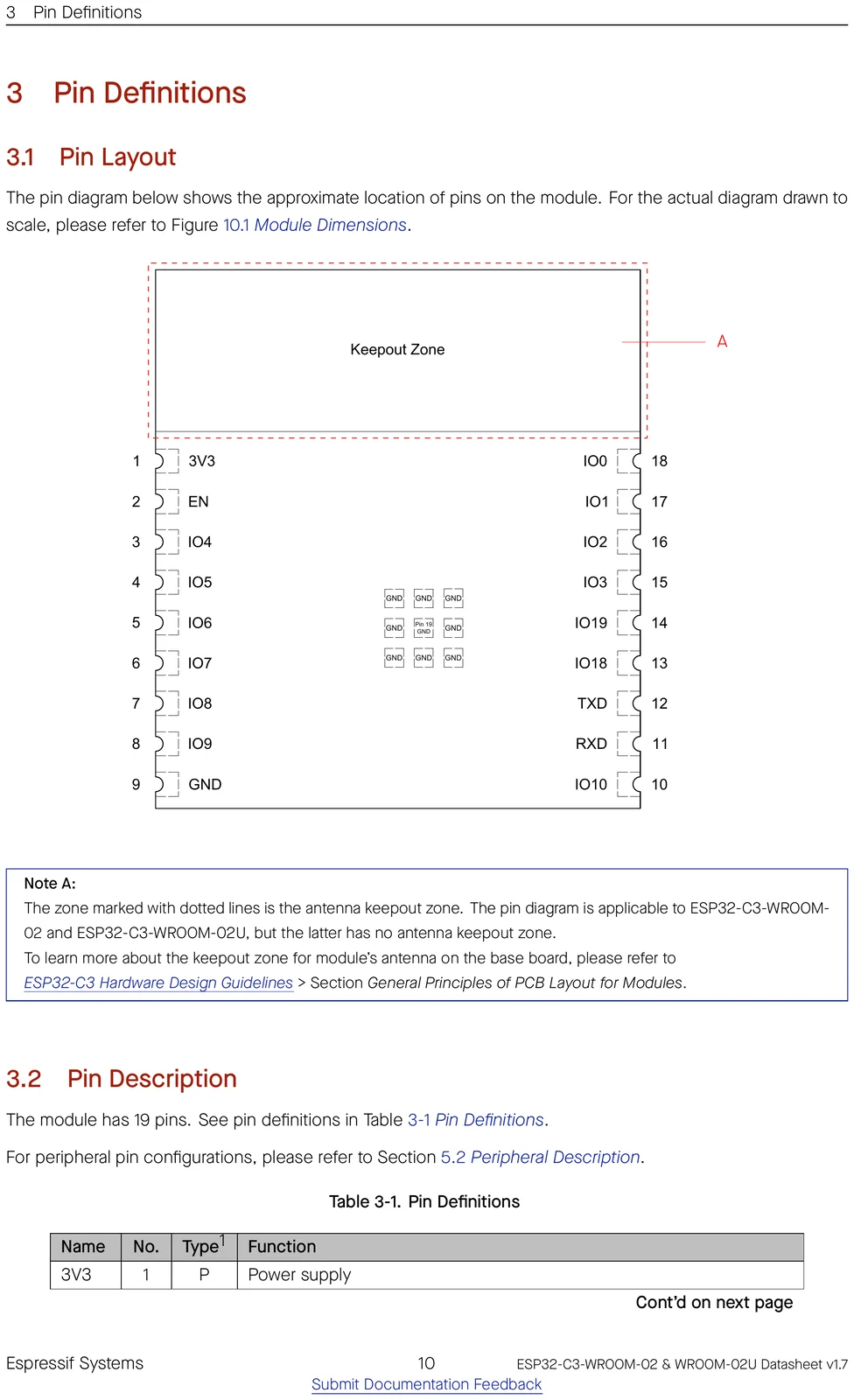
Pinout
⚑ flag an error| # | Name | Type | Functions | |
|---|---|---|---|---|
| 1 | 3V3 | P | Power supply | ⚑ |
| 2 | EN | I | Chip enable | ⚑ |
| 3 | IO4 | I/O/T | GPIO4, ADC1_CH4, FSPIHD, MTMS | ⚑ |
| 4 | IO5 | I/O/T | GPIO5, ADC2_CH0, FSPIWP, MTDI | ⚑ |
| 5 | IO6 | I/O/T | GPIO6, FSPICLK, MTCK | ⚑ |
| 6 | IO7 | I/O/T | GPIO7, FSPID, MTDO | ⚑ |
| 7 | IO8 | I/O/T | GPIO8 | ⚑ |
| 8 | IO9 | I/O/T | GPIO9 | ⚑ |
| 9,19 | GND | P | Ground | ⚑ |
| 10 | IO10 | I/O/T | GPIO10, FSPICS0 | ⚑ |
| 11 | RXD | I/O/T | GPIO20, U0RXD | ⚑ |
| 12 | TXD | I/O/T | GPIO21, U0TXD | ⚑ |
| 13 | IO18 | I/O/T | GPIO18, USB_D- | ⚑ |
| 14 | IO19 | I/O/T | GPIO19, USB_D+ | ⚑ |
| 15 | IO3 | I/O/T | GPIO3, ADC1_CH3 | ⚑ |
| 16 | IO2 | I/O/T | GPIO2, ADC1_CH2, FSPIQ | ⚑ |
| 17 | IO1 | I/O/T | GPIO1, ADC1_CH1, XTAL_32K_N | ⚑ |
| 18 | IO0 | I/O/T | GPIO0, ADC1_CH0, XTAL_32K_P | ⚑ |
Official datasheet pin-layout figure
Find a pin by function
Pick a capability to see which GPIOs provide it on the ESP32-C3.
Freely usable, no special role.
! Usable for general IO, but one function has a condition (e.g. ADC2 can’t be read while Wi-Fi is on) — see the note.
UART, I²C, SPI (master), I²S, PWM/LEDC and most digital peripherals route through the GPIO matrix — assign them to any pin from “Safe GPIO”. The categories above are the pins tied to a fixed function (analog, USB, crystal…) or that need care.
Strapping pins
⚑ flag an errorGPIOs sampled at reset — avoid driving these at power-up.
| Pin | Default | Bit | Function |
|---|---|---|---|
GPIO2 | floating | — | boot |
GPIO8 | floating | — | rom_log |
GPIO9 | pull-up | 1 | boot_mode |
GPIO pin warnings
⚑ flag an errorOn the ESP32-C3, almost any peripheral can be routed to almost any GPIO through the IO MUX, so most pins are free to use. These are the exceptions — pins with a fixed role or a boot-time behaviour to design around.
| Pin | Why it needs care |
|---|---|
GPIO2 | strapping pin (affects boot) |
GPIO4 | JTAG |
GPIO5 | JTAG |
GPIO6 | JTAG |
GPIO7 | JTAG |
GPIO8 | strapping pin (affects boot) |
GPIO9 | strapping pin (affects boot) |
GPIO18 | native USB D± |
GPIO19 | native USB D± |
GPIO20 | UART0 console (boot log) |
GPIO21 | UART0 console (boot log) |
- The ADC2 channels share hardware with the Wi-Fi radio, so ADC2 readings are unavailable while Wi-Fi is active — but those GPIOs are still free for any digital function. Use the ADC1 channels for analog input alongside Wi-Fi.
Compute & memory
⚑ flag an error| CPU | RISC-V, 1-core |
|---|---|
| Max clock | 160 MHz |
| SRAM | 400 KB |
| ROM | 384 KB |
| Flash options | 4 / 8 / 16 MB |
| PSRAM | None |
| Co-processor | none |
Wireless
⚑ flag an error| Wi-Fi | Wi-Fi 4 |
|---|---|
| Wi-Fi bands | 2.4GHz |
| Bluetooth | BLE 5.x |
| 802.15.4 (Thread/Zigbee) | No |
| Antenna | PCB |
Peripherals & I/O
⚑ flag an error| Usable GPIO | 15 |
|---|---|
| ADC | 6× 12-bit |
| USB | USB-Serial-JTAG |
| UART / SPI / I²C / I²S | 2 / 1 / 1 / 1 |
| TWAI (CAN) | Yes |
| SD/MMC | No |
| Ethernet MAC | No |
| Touch | 0 |
Power
⚑ flag an error| Operating voltage | 3.0-3.6 V |
|---|---|
| Deep sleep | 5 µA |
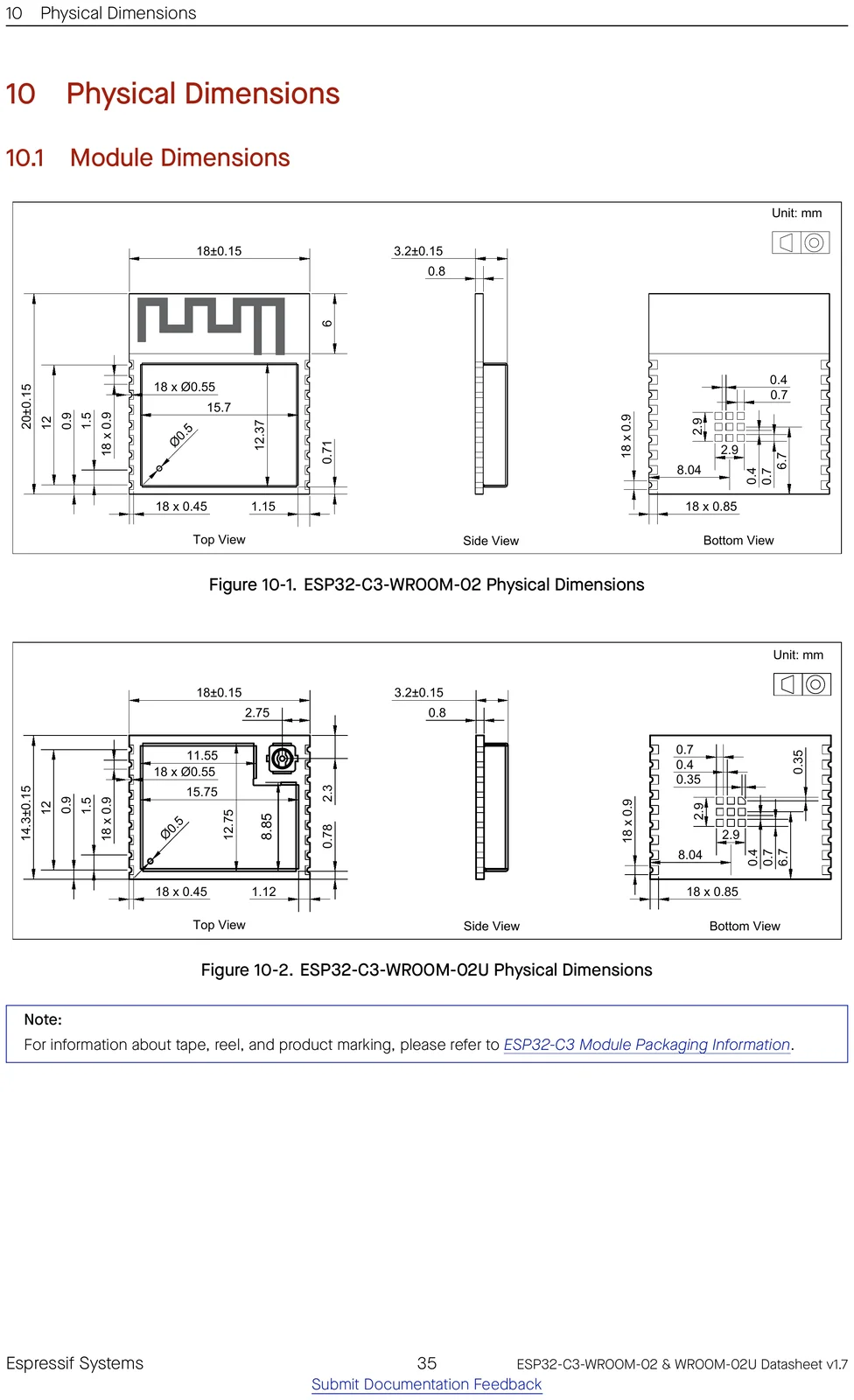
Physical
⚑ flag an error| Dimensions | 18 × 20 × 3.2 mm |
|---|---|
| Pin count | 19 |
| Temp range | -40 to 85 °C |
| Mounting | SMD castellated |
| Lifecycle | Active |
Security
⚑ flag an error| Secure boot | Yes |
|---|---|
| Flash encryption | Yes |
| Crypto | AES, SHA, RSA, HMAC, RNG |
| Digital signature | Yes |
| TRNG | Yes |
Ordering codes
⚑ flag an errorThe orderable part numbers and what each ships with — decoded from the suffix. Confirm against the latest datasheet before ordering.
| Part number | Flash | PSRAM | Temp |
|---|---|---|---|
ESP32-C3-WROOM-02-N4 | 4 MB | — | −40 to 85 °C |
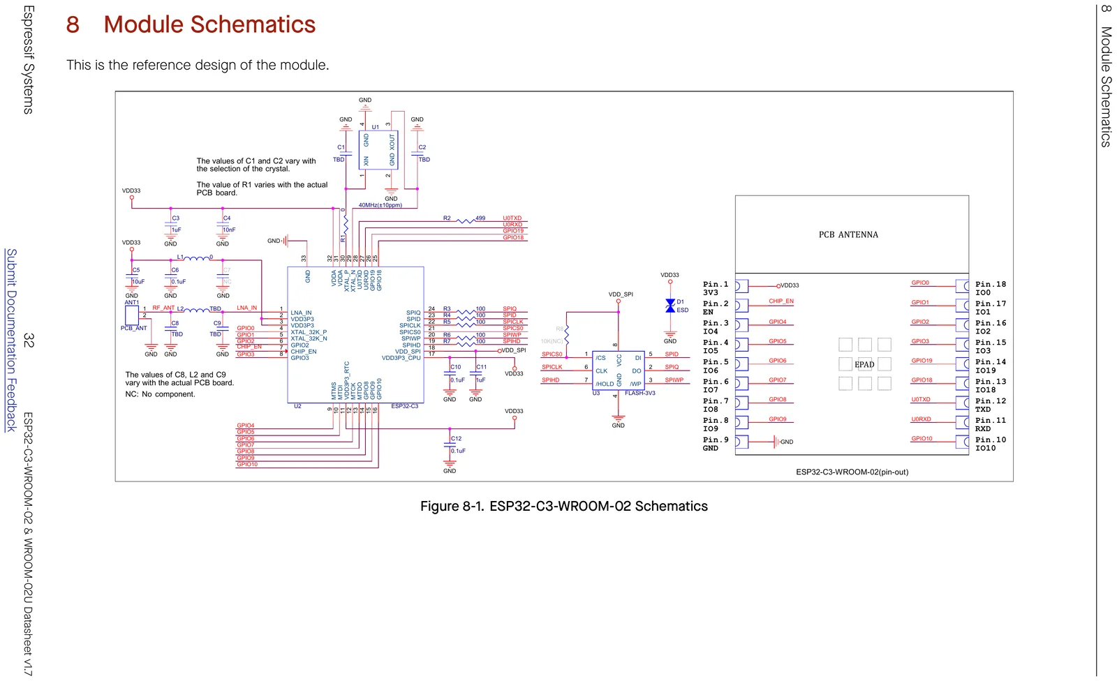
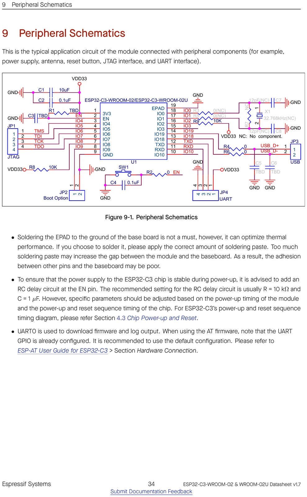
Schematics
Mechanical & CAD
Getting started
Frameworks: Arduino-ESP32 core — fully supported · ESP-IDF 4.3+ (Espressif's official SDK) · MicroPython · Matter.
ESP-IDF target: idf.py set-target esp32c3.
The SoC has a built-in USB Serial/JTAG controller, so you can flash and debug over its native USB port with no external adapter.
Open-source projects using this module
Public GitHub projects whose KiCad design files reference the ESP32-C3-WROOM-02.
- justbuchanan/oasis ★ 269
3d-printed smart terrarium
- lilka-dev/lilka ★ 225
Схема та документація ігрової консолі Lilka
- Spritetm/picframe_colepd ★ 96
A WiFi picture frame allowing for remote photo uploads, using an ESP32-C3 and a 5.6" color E-ink display
- Spritetm/esp32c3-doom-bauble ★ 88
Christmas tree bauble with an ESP32C3 running Doom
- ElektroJonas/DIY-Quadcopter ★ 57
This repository contains the control algorithm for a quadcopter drone on an ESP32 as well as electrical schematics and a pcb design.
- brown-studios/minuet ★ 56
Minuet upgrades your MAXXAIR Maxxfan with a brushless DC motor, home automation features, and accessories.
- mawoka-myblock/td-free ★ 50
Measure the TD of your filament easily
- ZhiFun/FunHome ★ 25
DIY design of smart home hardware based on Home Assistant.
Frequently asked questions
Does the ESP32-C3-WROOM-02 have Wi-Fi and Bluetooth?
It provides 2.4 GHz Wi-Fi 4 and Bluetooth LE.
How much memory does the ESP32-C3-WROOM-02 have?
It comes with 4, 8, 16 MB flash options and the ESP32-C3 has 400 KB of on-chip SRAM.
How many GPIO pins does the ESP32-C3-WROOM-02 have?
The module breaks out 15 GPIO, with up to 6 12-bit ADC channels. See the full pinout above.
Can I use the ESP32-C3-WROOM-02 with the Arduino IDE?
Yes — install the Arduino-ESP32 core and pick an ESP32-C3-based board. You can also use ESP-IDF 4.3 or MicroPython.
How do I flash the ESP32-C3-WROOM-02?
The SoC has a built-in USB Serial/JTAG controller, so you can flash and debug over its native USB port with no external adapter.
Is the ESP32-C3-WROOM-02 5 V tolerant?
No. It runs at 3.0-3.6 V and its GPIO are not 5 V tolerant — level-shift any 5 V signals.
Can I use an external antenna with the ESP32-C3-WROOM-02?
Most Espressif modules are also offered in a "-U" / "-1U" variant that swaps the on-board PCB antenna for a U.FL/IPEX connector for an external antenna — otherwise identical. Check this part's datasheet for the exact variant name.
Further reading
- ESP32-C3-WROOM-02 Datasheet
- ESP32-C3 modules
- Certificates for ESP32-C3-WROOM-02
- Espressif Product Selector
- ESP32-C3 Datasheet
- ESP32-C3 Technical Reference Manual
- ESP32-C3 product page
- ESP-IDF Programming Guide
- Hardware Design Guidelines
- ESP Dev-Kits documentation
- Espressif KiCad libraries (symbols/footprints/3D)