ESP32-PICO-MINI-02
PICO module · based on ESP32 (ESP32 (classic)) · Active
- Xtensa LX6
- 2× @ 240 MHz
- Wi-Fi 4
- BT Classic + BLE
- 8 MB flash
- 2 MB PSRAM
- 27 GPIO
- PCB antenna
As an affiliate we may earn from qualifying purchases. Prices and availability are set by AliExpress.
Every figure here is checked against Espressif’s official datasheets. We’ve taken every care to keep it accurate — but datasheets are dense and mistakes happen, so if something looks off, please report it.
The ESP32-PICO-MINI-02 is a system-in-package Espressif module built on the ESP32 dual-core Xtensa LX6 SoC clocked up to 240 MHz. It pairs 2.4 GHz Wi-Fi 4 and Bluetooth Classic + LE with 8 MB flash and up to 2 MB PSRAM, routes the radio to a PCB antenna, and breaks out 27 GPIO; the module measures 13.2 × 16.6 × 2.4 mm.
The extra PSRAM gives headroom for framebuffers, audio buffers and richer touch GUIs. Secure boot and flash encryption are available for production security. Espressif lists target uses including Smart Home, Audio Devices, Industrial Automation, Generic Low-power IoT Sensor Hubs and Health Care.
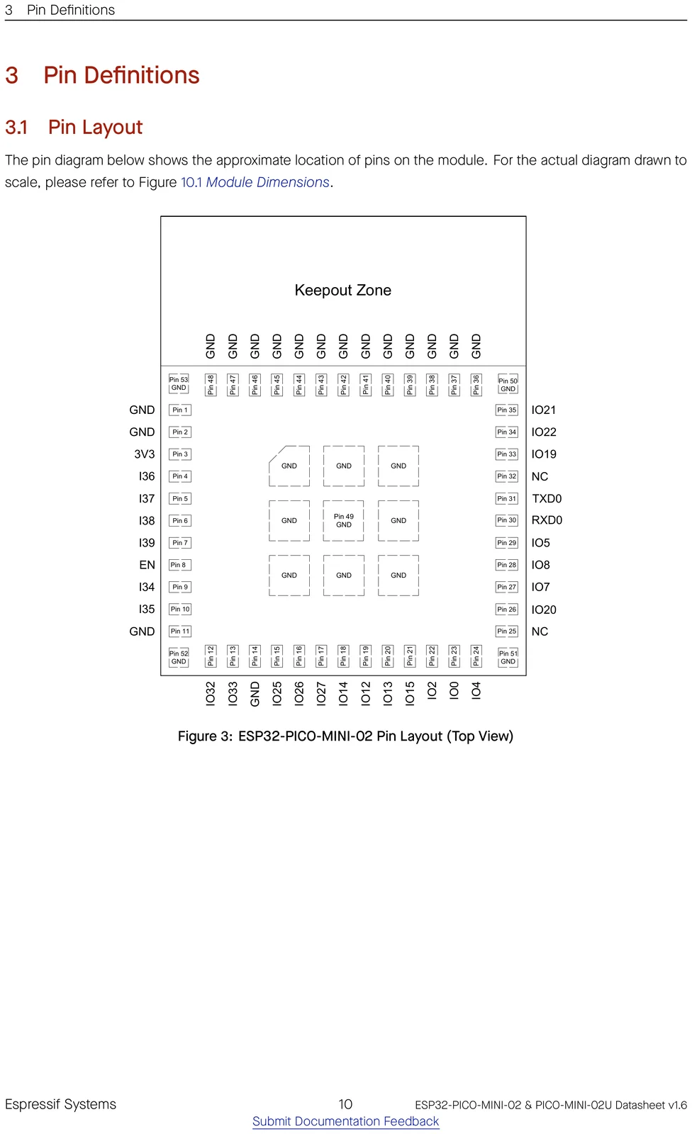
Pinout
⚑ flag an error| # | Name | Type | Functions | |
|---|---|---|---|---|
| 1, 2, 11, 14, 36~53 | GND | P | Ground | ⚑ |
| 3 | 3V3 | P | Power supply | ⚑ |
| 4 | I36 | I | GPIO36, ADC1_CH0, RTC_GPIO0 | ⚑ |
| 5 | I37 | I | GPIO37, ADC1_CH1, RTC_GPIO1 | ⚑ |
| 6 | I38 | I | GPIO38, ADC1_CH2, RTC_GPIO2 | ⚑ |
| 7 | I39 | I | GPIO39, ADC1_CH3, RTC_GPIO3 | ⚑ |
| 8 | EN | I | Chip enable | ⚑ |
| 9 | I34 | I | GPIO34, ADC1_CH6, RTC_GPIO4 | ⚑ |
| 10 | I35 | I | GPIO35, ADC1_CH7, RTC_GPIO5 | ⚑ |
| 12 | IO32 | I/O | GPIO32, XTAL_32K_P (32.768 kHz crystal oscillator input), ADC1_CH4, TOUCH9, RTC_GPIO9 | ⚑ |
| 13 | IO33 | I/O | GPIO33, XTAL_32K_N (32.768 kHz crystal oscillator output), ADC1_CH5, TOUCH8, RTC_GPIO8 | ⚑ |
| 15 | IO25 | I/O | GPIO25, DAC_1, ADC2_CH8, RTC_GPIO6, EMAC_RXD0 | ⚑ |
| 16 | IO26 | I/O | GPIO26, DAC_2, ADC2_CH9, RTC_GPIO7, EMAC_RXD1 | ⚑ |
| 17 | IO27 | I/O | GPIO27, ADC2_CH7, TOUCH7, RTC_GPIO17, EMAC_RX_DV | ⚑ |
| 18 | IO14 | I/O | GPIO14, ADC2_CH6, TOUCH6, RTC_GPIO16, MTMS, HSPICLK, HS2_CLK, SD_CLK, EMAC_TXD2 | ⚑ |
| 19 | IO12 | I/O | GPIO12, ADC2_CH5, TOUCH5, RTC_GPIO15, MTDI, HSPIQ, HS2_DATA2, SD_DATA2, EMAC_TXD3 | ⚑ |
| 20 | IO13 | I/O | GPIO13, ADC2_CH4, TOUCH4, RTC_GPIO14, MTCK, HSPID, HS2_DATA3, SD_DATA3, EMAC_RX_ER | ⚑ |
| 21 | IO15 | I/O | GPIO15, ADC2_CH3, TOUCH3, RTC_GPIO13, MTDO, HSPICS0, HS2_CMD, SD_CMD, EMAC_RXD3 | ⚑ |
| 22 | IO2 | I/O | GPIO2, ADC2_CH2, TOUCH2, RTC_GPIO12, HSPIWP, HS2_DATA0, SD_DATA0 | ⚑ |
| 23 | IO0 | I/O | GPIO0, ADC2_CH1, TOUCH1, RTC_GPIO11, CLK_OUT1, EMAC_TX_CLK | ⚑ |
| 24 | IO4 | I/O | GPIO4, ADC2_CH0, TOUCH0, RTC_GPIO10, HSPIHD, HS2_DATA1, SD_DATA1, EMAC_TX_ER | ⚑ |
| 25 | NC | - | - | ⚑ |
| 26 | IO20 | I/O | GPIO20 | ⚑ |
| 27 | IO7 | I/O | GPIO7, HS1_DATA0, U2RTS, SD_DATA0 | ⚑ |
| 28 | IO8 | I/O | GPIO8, HS1_DATA1, U2CTS, SD_DATA1 | ⚑ |
| 29 | IO5 | I/O | GPIO5, VSPICS0, HS1_DATA6, EMAC_RX_CLK | ⚑ |
| 30 | RXD0 | I/O | GPIO3, U0RXD, CLK_OUT2 | ⚑ |
| 31 | TXD0 | I/O | GPIO1, U0TXD, CLK_OUT3, EMAC_RXD2 | ⚑ |
| 32 | NC | - | - | ⚑ |
| 33 | IO19 | I/O | GPIO19, VSPIQ, U0CTS, EMAC_TXD0 | ⚑ |
| 34 | IO22 | I/O | GPIO22, VSPIWP, U0RTS, EMAC_TXD1 | ⚑ |
| 35 | IO21 | I/O | GPIO21, VSPIHD, EMAC_TX_EN | ⚑ |
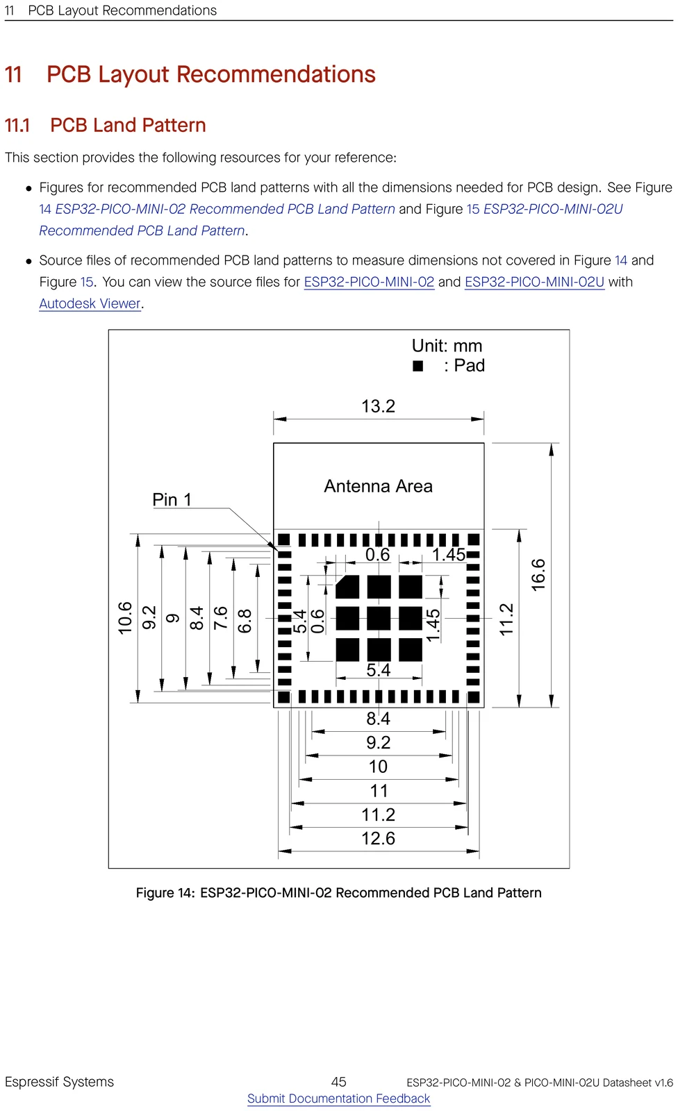
Official datasheet pin-layout figure
Find a pin by function
Pick a capability to see which GPIOs provide it on the ESP32.
Freely usable, no special role.
! Usable for general IO, but one function has a condition (e.g. ADC2 can’t be read while Wi-Fi is on) — see the note.
UART, I²C, SPI (master), I²S, PWM/LEDC and most digital peripherals route through the GPIO matrix — assign them to any pin from “Safe GPIO”. The categories above are the pins tied to a fixed function (analog, USB, crystal…) or that need care.
Strapping pins
⚑ flag an errorGPIOs sampled at reset — avoid driving these at power-up.
| Pin | Default | Bit | Function |
|---|---|---|---|
GPIO0 | pull-up | 1 | boot_mode |
GPIO2 | pull-down | 0 | boot |
MTDI | pull-down | 0 | flash_voltage |
MTDO | pull-up | 1 | rom_log |
GPIO5 | pull-up | 1 | sdio_timing |
GPIO pin warnings
⚑ flag an errorOn the ESP32, almost any peripheral can be routed to almost any GPIO through the IO MUX, so most pins are free to use. These are the exceptions — pins with a fixed role or a boot-time behaviour to design around.
| Pin | Why it needs care |
|---|---|
GPIO0 | strapping pin (affects boot) |
GPIO1 | UART0 console (boot log) |
GPIO2 | strapping pin (affects boot) |
GPIO3 | UART0 console (boot log) |
GPIO5 | strapping pin (affects boot) |
GPIO12 | strapping pin (affects boot); JTAG |
GPIO13 | JTAG |
GPIO14 | JTAG |
GPIO15 | strapping pin (affects boot); JTAG |
GPIO34 | input-only (no output/pull-up) |
GPIO35 | input-only (no output/pull-up) |
GPIO36 | input-only (no output/pull-up) |
GPIO37 | input-only (no output/pull-up) |
GPIO38 | input-only (no output/pull-up) |
GPIO39 | input-only (no output/pull-up) |
- The ADC2 channels share hardware with the Wi-Fi radio, so ADC2 readings are unavailable while Wi-Fi is active — but those GPIOs are still free for any digital function. Use the ADC1 channels for analog input alongside Wi-Fi.
Compute & memory
⚑ flag an error| CPU | Xtensa LX6, 2-core |
|---|---|
| Max clock | 240 MHz |
| SRAM | 520 KB |
| ROM | 448 KB |
| Flash options | 8 MB |
| PSRAM | 2 MB (quad) |
| Co-processor | ULP-FSM |
Wireless
⚑ flag an error| Wi-Fi | Wi-Fi 4 |
|---|---|
| Wi-Fi bands | 2.4GHz |
| Bluetooth | BT Classic + BLE |
| 802.15.4 (Thread/Zigbee) | No |
| Antenna | PCB |
Peripherals & I/O
⚑ flag an error| Usable GPIO | 27 |
|---|---|
| ADC | 18× 12-bit |
| USB | USB-Serial(external) |
| UART / SPI / I²C / I²S | 3 / 2 / 2 / 2 |
| TWAI (CAN) | Yes |
| SD/MMC | Yes |
| Ethernet MAC | Yes |
| Touch | 10 |
Power
⚑ flag an error| Operating voltage | 3.0-3.6 V |
|---|---|
| Deep sleep | 10 µA |
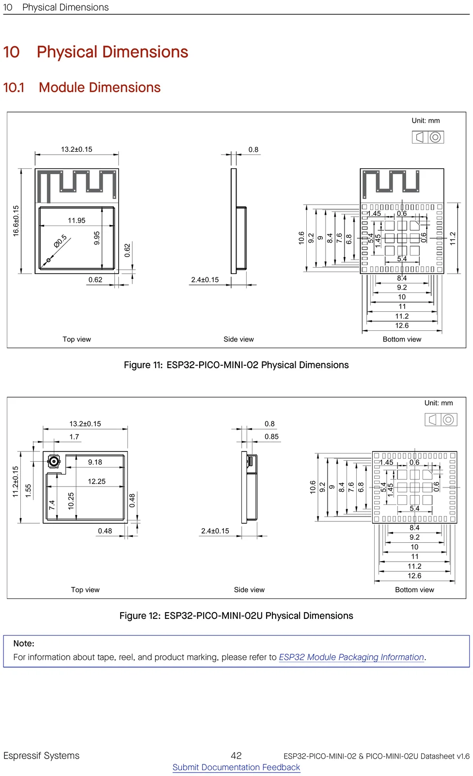
Physical
⚑ flag an error| Dimensions | 13.2 × 16.6 × 2.4 mm |
|---|---|
| Pin count | 31 |
| Temp range | -40 to 85 °C |
| Mounting | SMD castellated |
| Lifecycle | Active |
Security
⚑ flag an error| Secure boot | Yes |
|---|---|
| Flash encryption | Yes |
| Crypto | AES, SHA, RSA, RNG |
| Digital signature | No |
| TRNG | Yes |
Ordering codes
⚑ flag an errorThe orderable part numbers and what each ships with — decoded from the suffix. Confirm against the latest datasheet before ordering.
| Part number | Flash | PSRAM | Temp |
|---|---|---|---|
ESP32-PICO-MINI-02-N8R2 | 8 MB | 2 MB (quad) | −40 to 85 °C |
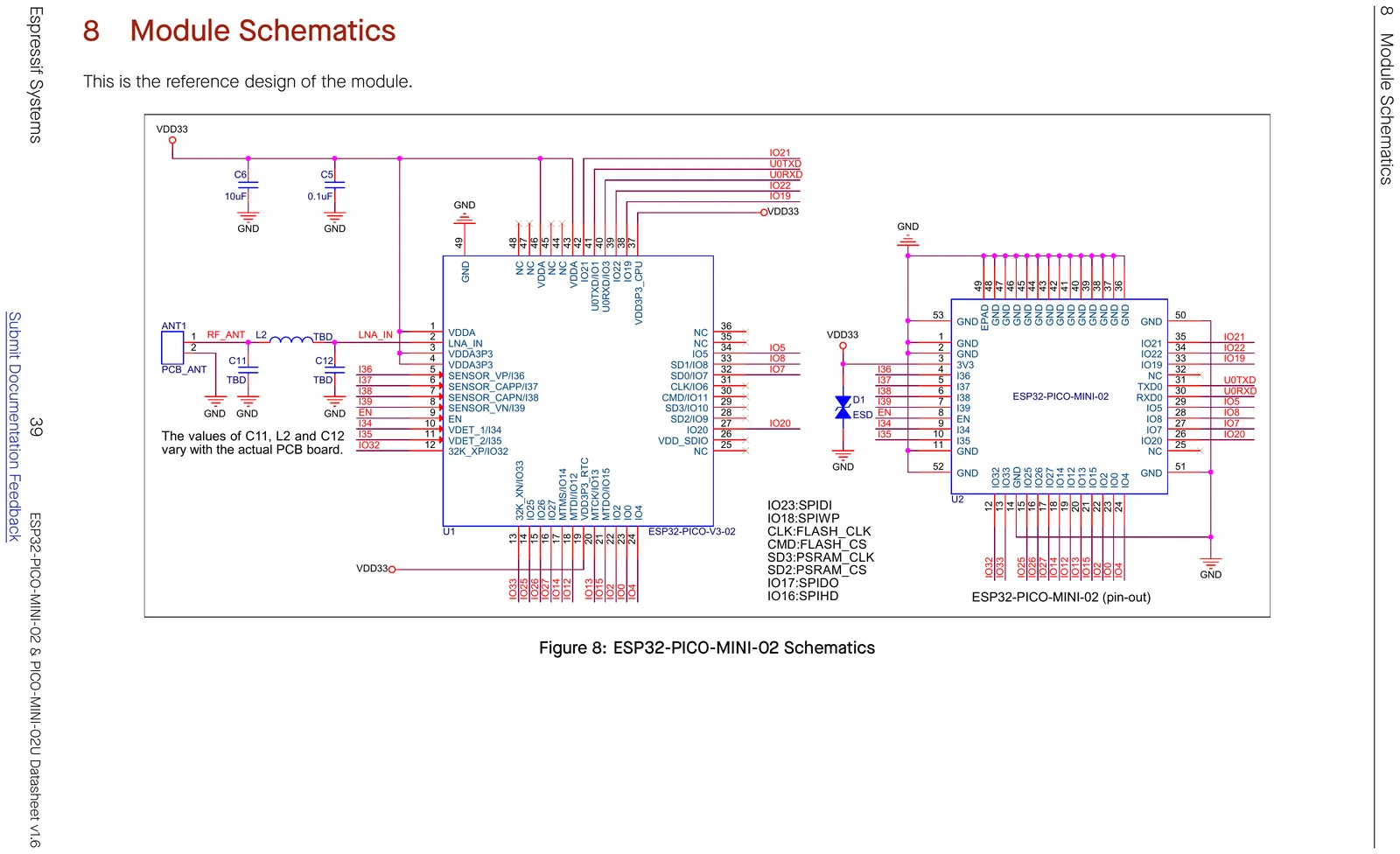
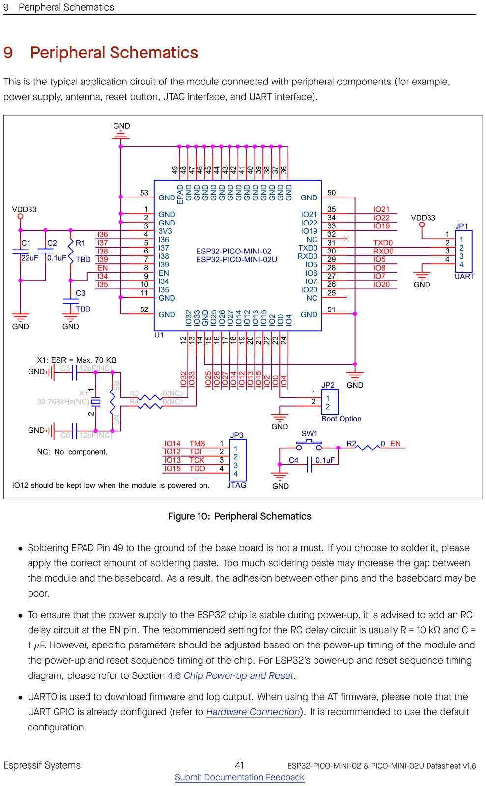
Schematics
Mechanical & CAD
Getting started
Frameworks: Arduino-ESP32 core — fully supported · ESP-IDF 3.0+ (Espressif's official SDK) · MicroPython.
ESP-IDF target: idf.py set-target esp32.
Programming uses UART — most dev boards include a USB-to-UART bridge; for the bare module add your own (e.g. CP2102/CH340).
Open-source projects using this module
Public GitHub projects whose KiCad design files reference the ESP32-PICO-MINI-02.
- greghulette/Wireless_Communication_Board-WCB ★ 12
Repository for the Wireless Commuincation Board (WCB)
- opendata-nuernberg/open-sensor-platform ★ 2
Hardware Designs and Firmware of the Open Sensor Platform
Frequently asked questions
Does the ESP32-PICO-MINI-02 have Wi-Fi and Bluetooth?
It provides 2.4 GHz Wi-Fi 4 and Bluetooth Classic + LE.
How much memory does the ESP32-PICO-MINI-02 have?
It comes with 8 MB of flash, up to 2 MB of PSRAM, and the ESP32 has 520 KB of on-chip SRAM.
How many GPIO pins does the ESP32-PICO-MINI-02 have?
The module breaks out 27 GPIO, with up to 18 12-bit ADC channels. See the full pinout above.
Can I use the ESP32-PICO-MINI-02 with the Arduino IDE?
Yes — install the Arduino-ESP32 core and pick an ESP32-based board. You can also use ESP-IDF 3.0 or MicroPython.
How do I flash the ESP32-PICO-MINI-02?
Programming uses UART — most dev boards include a USB-to-UART bridge; for the bare module add your own (e.g. CP2102/CH340).
Is the ESP32-PICO-MINI-02 5 V tolerant?
No. It runs at 3.0-3.6 V and its GPIO are not 5 V tolerant — level-shift any 5 V signals.
Can I use an external antenna with the ESP32-PICO-MINI-02?
Most Espressif modules are also offered in a "-U" / "-1U" variant that swaps the on-board PCB antenna for a U.FL/IPEX connector for an external antenna — otherwise identical. Check this part's datasheet for the exact variant name.