ESP32-S3-MINI-1
MINI module · based on ESP32-S3 · Active
- Xtensa LX7
- 2× @ 240 MHz
- Wi-Fi 4
- BLE 5.x
- 4 / 8 MB flash
- 2 MB PSRAM
- 39 GPIO
- PCB antenna
As an affiliate we may earn from qualifying purchases. Prices and availability are set by AliExpress.
Interactive 3D model · drag to rotate
Every figure here is checked against Espressif’s official datasheets. We’ve taken every care to keep it accurate — but datasheets are dense and mistakes happen, so if something looks off, please report it.
The ESP32-S3-MINI-1 is a compact Espressif module built on the ESP32-S3 dual-core Xtensa LX7 SoC clocked up to 240 MHz. It pairs 2.4 GHz Wi-Fi 4 and Bluetooth LE with up to 8 MB flash and up to 2 MB PSRAM, routes the radio to a PCB antenna, and breaks out 39 GPIO; the module measures 15.4 × 20.5 × 2.4 mm.
PSRAM together with the SoC's vector (AI) instructions makes it a strong fit for camera, audio and on-device ML projects. Secure boot and flash encryption are available for production security. Espressif lists target uses including Smart Home, POS Machines, Industrial Automation, Service Robot and Health Care.
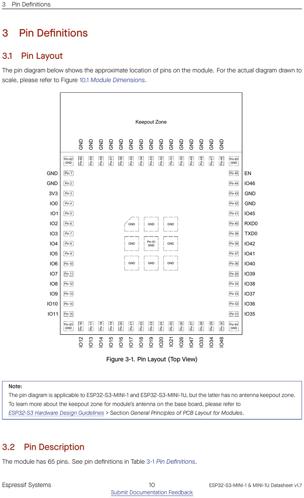
Pinout
⚑ flag an error| # | Name | Type | Functions | |
|---|---|---|---|---|
| 1, 2, 42, 43, 46~65 | GND | P | Ground | ⚑ |
| 3 | 3V3 | P | Power supply | ⚑ |
| 4 | IO0 | I/O/T | RTC_GPIO0, GPIO0 | ⚑ |
| 5 | IO1 | I/O/T | RTC_GPIO1, GPIO1, TOUCH1, ADC1_CH0 | ⚑ |
| 6 | IO2 | I/O/T | RTC_GPIO2, GPIO2, TOUCH2, ADC1_CH1 | ⚑ |
| 7 | IO3 | I/O/T | RTC_GPIO3, GPIO3, TOUCH3, ADC1_CH2 | ⚑ |
| 8 | IO4 | I/O/T | RTC_GPIO4, GPIO4, TOUCH4, ADC1_CH3 | ⚑ |
| 9 | IO5 | I/O/T | RTC_GPIO5, GPIO5, TOUCH5, ADC1_CH4 | ⚑ |
| 10 | IO6 | I/O/T | RTC_GPIO6, GPIO6, TOUCH6, ADC1_CH5 | ⚑ |
| 11 | IO7 | I/O/T | RTC_GPIO7, GPIO7, TOUCH7, ADC1_CH6 | ⚑ |
| 12 | IO8 | I/O/T | RTC_GPIO8, GPIO8, TOUCH8, ADC1_CH7, SUBSPICS1 | ⚑ |
| 13 | IO9 | I/O/T | RTC_GPIO9, GPIO9, TOUCH9, ADC1_CH8, FSPIHD, SUBSPIHD | ⚑ |
| 14 | IO10 | I/O/T | RTC_GPIO10, GPIO10, TOUCH10, ADC1_CH9, FSPICS0, FSPIIO4, SUBSPICS0 | ⚑ |
| 15 | IO11 | I/O/T | RTC_GPIO11, GPIO11, TOUCH11, ADC2_CH0, FSPID, FSPIIO5, SUBSPID | ⚑ |
| 16 | IO12 | I/O/T | RTC_GPIO12, GPIO12, TOUCH12, ADC2_CH1, FSPICLK, FSPIIO6, SUBSPICLK | ⚑ |
| 17 | IO13 | I/O/T | RTC_GPIO13, GPIO13, TOUCH13, ADC2_CH2, FSPIQ, FSPIIO7, SUBSPIQ | ⚑ |
| 18 | IO14 | I/O/T | RTC_GPIO14, GPIO14, TOUCH14, ADC2_CH3, FSPIWP, FSPIDQS, SUBSPIWP | ⚑ |
| 19 | IO15 | I/O/T | RTC_GPIO15, GPIO15, U0RTS, ADC2_CH4, XTAL_32K_P | ⚑ |
| 20 | IO16 | I/O/T | RTC_GPIO16, GPIO16, U0CTS, ADC2_CH5, XTAL_32K_N | ⚑ |
| 21 | IO17 | I/O/T | RTC_GPIO17, GPIO17, U1TXD, ADC2_CH6 | ⚑ |
| 22 | IO18 | I/O/T | RTC_GPIO18, GPIO18, U1RXD, ADC2_CH7, CLK_OUT3 | ⚑ |
| 23 | IO19 | I/O/T | RTC_GPIO19, GPIO19, U1RTS, ADC2_CH8, CLK_OUT2, USB_D- | ⚑ |
| 24 | IO20 | I/O/T | RTC_GPIO20, GPIO20, U1CTS, ADC2_CH9, CLK_OUT1, USB_D+ | ⚑ |
| 25 | IO21 | I/O/T | RTC_GPIO21, GPIO21 | ⚑ |
| 26 | IO26b | I/O/T | SPICS1, GPIO26 | ⚑ |
| 27 | IO47 | I/O/T | SPICLK_P_DIFF, GPIO47, SUBSPICLK_P_DIFF | ⚑ |
| 28 | IO33 | I/O/T | SPIIO4, GPIO33, FSPIHD, SUBSPIHD | ⚑ |
| 29 | IO34 | I/O/T | SPIIO5, GPIO34, FSPICS0, SUBSPICS0 | ⚑ |
| 30 | IO48 | I/O/T | SPICLK_N_DIFF, GPIO48, SUBSPICLK_N_DIFF | ⚑ |
| 31 | IO35 | I/O/T | SPIIO6, GPIO35, FSPID, SUBSPID | ⚑ |
| 32 | IO36 | I/O/T | SPIIO7, GPIO36, FSPICLK, SUBSPICLK | ⚑ |
| 33 | IO37 | I/O/T | SPIDQS, GPIO37, FSPIQ, SUBSPIQ | ⚑ |
| 34 | IO38 | I/O/T | GPIO38, FSPIWP, SUBSPIWP | ⚑ |
| 35 | IO39 | I/O/T | MTCK, GPIO39, CLK_OUT3, SUBSPICS1 | ⚑ |
| 36 | IO40 | I/O/T | MTDO, GPIO40, CLK_OUT2 | ⚑ |
| 37 | IO41 | I/O/T | MTDI, GPIO41, CLK_OUT1 | ⚑ |
| 38 | IO42 | I/O/T | MTMS, GPIO42 | ⚑ |
| 39 | TXD0 | I/O/T | U0TXD, GPIO43, CLK_OUT1 | ⚑ |
| 40 | RXD0 | I/O/T | U0RXD, GPIO44, CLK_OUT2 | ⚑ |
| 41 | IO45 | I/O/T | GPIO45 | ⚑ |
| 44 | IO46 | I/O/T | GPIO46 | ⚑ |
| 45 | EN | I | Chip enable | ⚑ |
Official datasheet pin-layout figure
Find a pin by function
Pick a capability to see which GPIOs provide it on the ESP32-S3.
Freely usable, no special role.
! Usable for general IO, but one function has a condition (e.g. ADC2 can’t be read while Wi-Fi is on) — see the note.
UART, I²C, SPI (master), I²S, PWM/LEDC and most digital peripherals route through the GPIO matrix — assign them to any pin from “Safe GPIO”. The categories above are the pins tied to a fixed function (analog, USB, crystal…) or that need care.
Strapping pins
⚑ flag an errorGPIOs sampled at reset — avoid driving these at power-up.
| Pin | Default | Bit | Function |
|---|---|---|---|
GPIO0 | pull-up | 1 | boot_mode |
GPIO3 | floating | — | jtag |
GPIO45 | pull-down | 0 | flash_voltage |
GPIO46 | pull-down | 0 | boot |
GPIO pin warnings
⚑ flag an errorOn the ESP32-S3, almost any peripheral can be routed to almost any GPIO through the IO MUX, so most pins are free to use. These are the exceptions — pins with a fixed role or a boot-time behaviour to design around.
| Pin | Why it needs care |
|---|---|
GPIO0 | strapping pin (affects boot) |
GPIO3 | strapping pin (affects boot) |
GPIO19 | native USB D± |
GPIO20 | native USB D± |
GPIO39 | JTAG |
GPIO40 | JTAG |
GPIO41 | JTAG |
GPIO42 | JTAG |
GPIO43 | UART0 console (boot log) |
GPIO44 | UART0 console (boot log) |
GPIO45 | strapping pin (affects boot) |
GPIO46 | strapping pin (affects boot) |
- The ADC2 channels share hardware with the Wi-Fi radio, so ADC2 readings are unavailable while Wi-Fi is active — but those GPIOs are still free for any digital function. Use the ADC1 channels for analog input alongside Wi-Fi.
- Power-up glitches: GPIO1–GPIO18 emit a brief (~60 µs) low pulse at power-up, and GPIO18/19/20 also glitch high. Don’t drive glitch-sensitive loads (relay coils, MOSFET gates) directly from these without a pull resistor, and prefer gpio_config() over gpio_reset_pin() to set the output state cleanly.
- GPIO21 has field reports of Wi-Fi interference on some modules. If you see Wi-Fi instability with a peripheral on GPIO21, try lowering Wi-Fi TX power to ~11–13 dBm or moving the peripheral elsewhere.
Compute & memory
⚑ flag an error| CPU | Xtensa LX7, 2-core |
|---|---|
| Max clock | 240 MHz |
| SRAM | 512 KB |
| ROM | 384 KB |
| Flash options | 4 / 8 MB |
| PSRAM | 2 MB (quad) |
| Co-processor | ULP-RISC-V |
Wireless
⚑ flag an error| Wi-Fi | Wi-Fi 4 |
|---|---|
| Wi-Fi bands | 2.4GHz |
| Bluetooth | BLE 5.x |
| 802.15.4 (Thread/Zigbee) | No |
| Antenna | PCB |
Peripherals & I/O
⚑ flag an error| Usable GPIO | 39 |
|---|---|
| ADC | 20× 12-bit |
| USB | USB-OTG |
| UART / SPI / I²C / I²S | 3 / 2 / 2 / 2 |
| TWAI (CAN) | Yes |
| SD/MMC | Yes |
| Ethernet MAC | No |
| Touch | 14 |
Power
⚑ flag an error| Operating voltage | 3.0-3.6 V |
|---|---|
| Deep sleep | 7 µA |
Physical
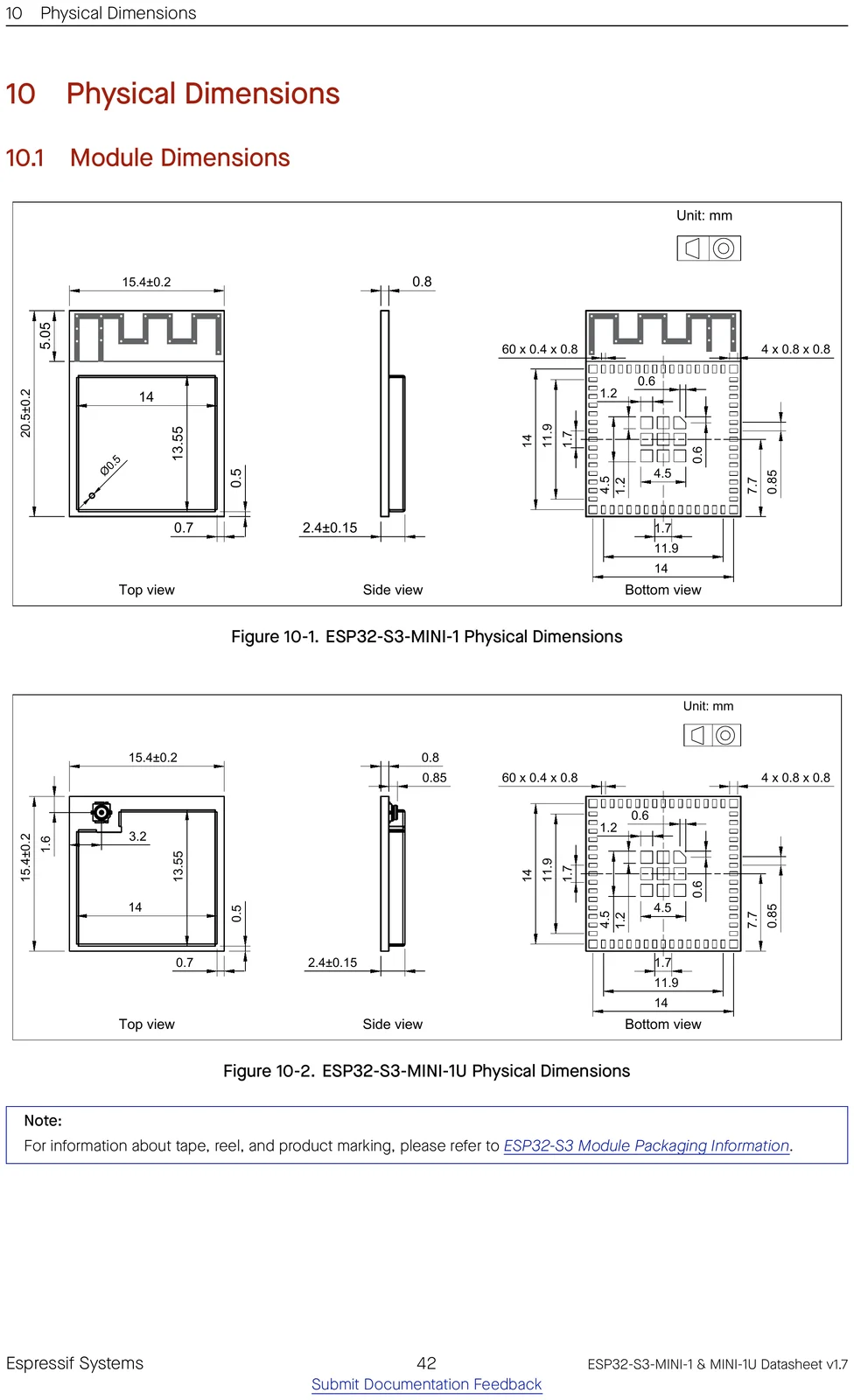
⚑ flag an error| Dimensions | 15.4 × 20.5 × 2.4 mm |
|---|---|
| Pin count | 41 |
| Temp range | -40 to 85 °C |
| Mounting | SMD castellated |
| Lifecycle | Active |
Security
⚑ flag an error| Secure boot | Yes |
|---|---|
| Flash encryption | Yes |
| Crypto | AES, SHA, RSA, HMAC, RNG |
| Digital signature | Yes |
| TRNG | Yes |
Ordering codes
⚑ flag an errorThe orderable part numbers and what each ships with — decoded from the suffix. Confirm against the latest datasheet before ordering.
| Part number | Flash | PSRAM | Temp |
|---|---|---|---|
ESP32-S3-MINI-1-N8 | 8 MB | — | −40 to 85 °C |
ESP32-S3-MINI-1-N4R2 | 4 MB | 2 MB (quad) | −40 to 85 °C |
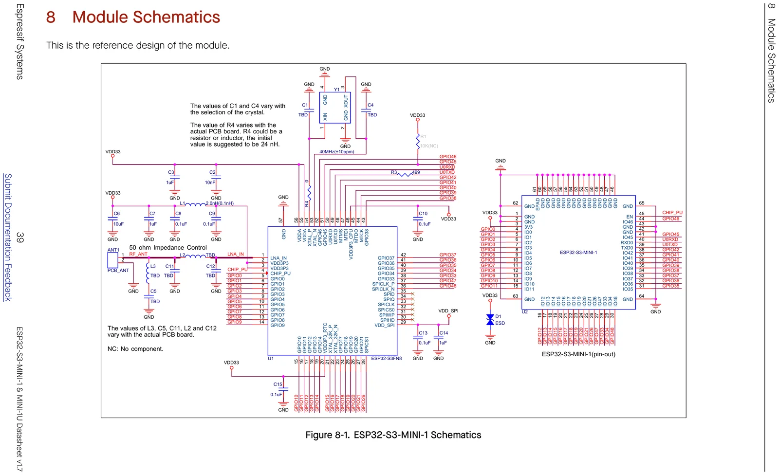
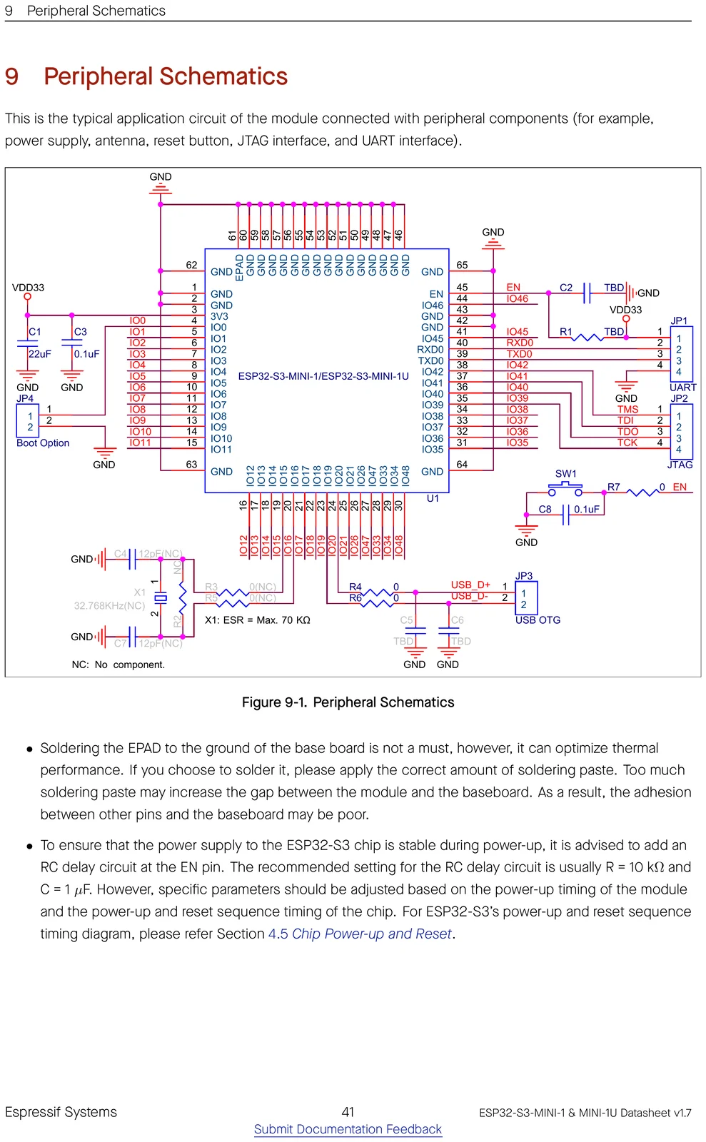
Schematics
Mechanical & CAD
Getting started
Frameworks: Arduino-ESP32 core — fully supported · ESP-IDF 4.4+ (Espressif's official SDK) · MicroPython · Matter.
ESP-IDF target: idf.py set-target esp32s3.
The SoC has native USB-OTG, so it can flash over USB and act as a USB device or host.
- Give the module a 3.3 V supply rated for at least 500 mA — RF transmit bursts pull well above the average current.
- EN is only weakly pulled high internally (~2 MΩ), which often isn’t reliable on its own. Add an external 100 kΩ pull-up, and for clean resets — especially with large bulk capacitance on the 3.3 V rail — use a reset-supervisor IC (e.g. MAX809) rather than just an RC network.
- Routing SPI (or most peripherals) through the GPIO matrix caps the SPI clock at 80 MHz; to run faster, use the dedicated IO_MUX pins.
Open-source projects using this module
Public GitHub projects whose KiCad design files reference the ESP32-S3-MINI-1.
- elipsitz/gamebub ★ 849
Open-source FPGA retro emulation handheld
- bread-modular/bread-modular ★ 63
Modular Synths for Everyone
- ISSUIUC/ISS-PCB ★ 28
Building custom flight computers
Frequently asked questions
Does the ESP32-S3-MINI-1 have Wi-Fi and Bluetooth?
It provides 2.4 GHz Wi-Fi 4 and Bluetooth LE.
How much memory does the ESP32-S3-MINI-1 have?
It comes with 4, 8 MB flash options, up to 2 MB of PSRAM, and the ESP32-S3 has 512 KB of on-chip SRAM.
How many GPIO pins does the ESP32-S3-MINI-1 have?
The module breaks out 39 GPIO, with up to 20 12-bit ADC channels. See the full pinout above.
Can I use the ESP32-S3-MINI-1 with the Arduino IDE?
Yes — install the Arduino-ESP32 core and pick an ESP32-S3-based board. You can also use ESP-IDF 4.4 or MicroPython.
How do I flash the ESP32-S3-MINI-1?
The SoC has native USB-OTG, so it can flash over USB and act as a USB device or host.
Is the ESP32-S3-MINI-1 5 V tolerant?
No. It runs at 3.0-3.6 V and its GPIO are not 5 V tolerant — level-shift any 5 V signals.
Can I use an external antenna with the ESP32-S3-MINI-1?
Most Espressif modules are also offered in a "-U" / "-1U" variant that swaps the on-board PCB antenna for a U.FL/IPEX connector for an external antenna — otherwise identical. Check this part's datasheet for the exact variant name.