ESP32-S3-WROOM-2
WROOM module · based on ESP32-S3 · Active
- Xtensa LX7
- 2× @ 240 MHz
- Wi-Fi 4
- BLE 5.x
- 16 / 32 MB flash
- 8 / 16 MB PSRAM
- 33 GPIO
- PCB antenna
As an affiliate we may earn from qualifying purchases. Prices and availability are set by AliExpress.
Every figure here is checked against Espressif’s official datasheets. We’ve taken every care to keep it accurate — but datasheets are dense and mistakes happen, so if something looks off, please report it.
The ESP32-S3-WROOM-2 is a general-purpose Espressif module built on the ESP32-S3 dual-core Xtensa LX7 SoC clocked up to 240 MHz. It pairs 2.4 GHz Wi-Fi 4 and Bluetooth LE with up to 32 MB flash and up to 16 MB PSRAM, routes the radio to a PCB antenna, and breaks out 33 GPIO; the module measures 18 × 25.5 × 3.1 mm.
PSRAM together with the SoC's vector (AI) instructions makes it a strong fit for camera, audio and on-device ML projects. Secure boot and flash encryption are available for production security. Espressif lists target uses including Smart Home, Smart Agriculture, Industrial Automation, POS Machines and Health Care.
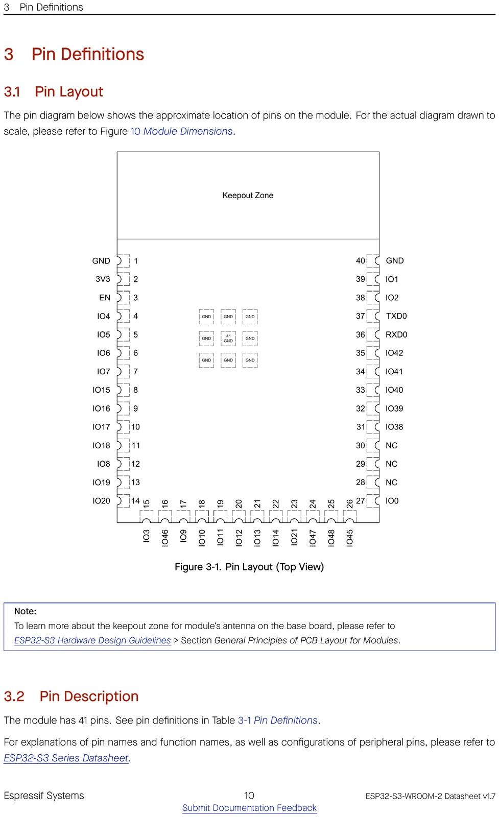
Pinout
⚑ flag an error| # | Name | Type | Functions | |
|---|---|---|---|---|
| 1 | GND | P | Ground | ⚑ |
| 2 | 3V3 | P | Power supply | ⚑ |
| 3 | EN | I | Chip enable | ⚑ |
| 4 | IO4 | I/O/T | RTC_GPIO4, GPIO4, TOUCH4, ADC1_CH3 | ⚑ |
| 5 | IO5 | I/O/T | RTC_GPIO5, GPIO5, TOUCH5, ADC1_CH4 | ⚑ |
| 6 | IO6 | I/O/T | RTC_GPIO6, GPIO6, TOUCH6, ADC1_CH5 | ⚑ |
| 7 | IO7 | I/O/T | RTC_GPIO7, GPIO7, TOUCH7, ADC1_CH6 | ⚑ |
| 8 | IO15 | I/O/T | RTC_GPIO15, GPIO15, U0RTS, ADC2_CH4, XTAL_32K_P | ⚑ |
| 9 | IO16 | I/O/T | RTC_GPIO16, GPIO16, U0CTS, ADC2_CH5, XTAL_32K_N | ⚑ |
| 10 | IO17 | I/O/T | RTC_GPIO17, GPIO17, U1TXD, ADC2_CH6 | ⚑ |
| 11 | IO18 | I/O/T | RTC_GPIO18, GPIO18, U1RXD, ADC2_CH7, CLK_OUT3 | ⚑ |
| 12 | IO8 | I/O/T | RTC_GPIO8, GPIO8, TOUCH8, ADC1_CH7, SUBSPICS1 | ⚑ |
| 13 | IO19 | I/O/T | RTC_GPIO19, GPIO19, U1RTS, ADC2_CH8, CLK_OUT2, USB_D- | ⚑ |
| 14 | IO20 | I/O/T | RTC_GPIO20, GPIO20, U1CTS, ADC2_CH9, CLK_OUT1, USB_D+ | ⚑ |
| 15 | IO3 | I/O/T | RTC_GPIO3, GPIO3, TOUCH3, ADC1_CH2 | ⚑ |
| 16 | IO46 | I/O/T | GPIO46 | ⚑ |
| 17 | IO9 | I/O/T | RTC_GPIO9, GPIO9, TOUCH9, ADC1_CH8, FSPIHD, SUBSPIHD | ⚑ |
| 18 | IO10 | I/O/T | RTC_GPIO10, GPIO10, TOUCH10, ADC1_CH9, FSPICS0, FSPIIO4, SUBSPICS0 | ⚑ |
| 19 | IO11 | I/O/T | RTC_GPIO11, GPIO11, TOUCH11, ADC2_CH0, FSPID, FSPIIO5, SUBSPID | ⚑ |
| 20 | IO12 | I/O/T | RTC_GPIO12, GPIO12, TOUCH12, ADC2_CH1, FSPICLK, FSPIIO6, SUBSPICLK | ⚑ |
| 21 | IO13 | I/O/T | RTC_GPIO13, GPIO13, TOUCH13, ADC2_CH2, FSPIQ, FSPIIO7, SUBSPIQ | ⚑ |
| 22 | IO14 | I/O/T | RTC_GPIO14, GPIO14, TOUCH14, ADC2_CH3, FSPIWP, FSPIDQS, SUBSPIWP | ⚑ |
| 23 | IO21 | I/O/T | RTC_GPIO21, GPIO21 | ⚑ |
| 24 | IO47 | I/O/T | SPICLK_P_DIFF, GPIO47, SUBSPICLK_P_DIFF | ⚑ |
| 25 | IO48 | I/O/T | SPICLK_N_DIFF, GPIO48, SUBSPICLK_N_DIFF | ⚑ |
| 26 | IO45 | I/O/T | GPIO45 | ⚑ |
| 27 | IO0 | I/O/T | RTC_GPIO0, GPIO0 | ⚑ |
| 28 | NC | - | NC | ⚑ |
| 29 | NC | - | NC | ⚑ |
| 30 | NC | - | NC | ⚑ |
| 31 | IO38 | I/O/T | GPIO38, FSPIWP, SUBSPIWP | ⚑ |
| 32 | IO39 | I/O/T | MTCK, GPIO39, CLK_OUT3, SUBSPICS1 | ⚑ |
| 33 | IO40 | I/O/T | MTDO, GPIO40, CLK_OUT2 | ⚑ |
| 34 | IO41 | I/O/T | MTDI, GPIO41, CLK_OUT1 | ⚑ |
| 35 | IO42 | I/O/T | MTMS, GPIO42 | ⚑ |
| 36 | RXD0 | I/O/T | U0RXD, GPIO44, CLK_OUT2 | ⚑ |
| 37 | TXD0 | I/O/T | U0TXD, GPIO43, CLK_OUT1 | ⚑ |
| 38 | IO2 | I/O/T | RTC_GPIO2, GPIO2, TOUCH2, ADC1_CH1 | ⚑ |
| 39 | IO1 | I/O/T | RTC_GPIO1, GPIO1, TOUCH1, ADC1_CH0 | ⚑ |
| 40 | GND | P | Ground | ⚑ |
| 41 | EPAD | P | Ground | ⚑ |
Official datasheet pin-layout figure
Find a pin by function
Pick a capability to see which GPIOs provide it on the ESP32-S3.
Freely usable, no special role.
! Usable for general IO, but one function has a condition (e.g. ADC2 can’t be read while Wi-Fi is on) — see the note.
UART, I²C, SPI (master), I²S, PWM/LEDC and most digital peripherals route through the GPIO matrix — assign them to any pin from “Safe GPIO”. The categories above are the pins tied to a fixed function (analog, USB, crystal…) or that need care.
Strapping pins
⚑ flag an errorGPIOs sampled at reset — avoid driving these at power-up.
| Pin | Default | Bit | Function |
|---|---|---|---|
GPIO0 | pull-up | 1 | boot_mode |
GPIO3 | floating | — | jtag |
GPIO45 | pull-down | 0 | flash_voltage |
GPIO46 | pull-down | 0 | boot |
GPIO pin warnings
⚑ flag an errorOn the ESP32-S3, almost any peripheral can be routed to almost any GPIO through the IO MUX, so most pins are free to use. These are the exceptions — pins with a fixed role or a boot-time behaviour to design around.
| Pin | Why it needs care |
|---|---|
GPIO0 | strapping pin (affects boot) |
GPIO3 | strapping pin (affects boot) |
GPIO19 | native USB D± |
GPIO20 | native USB D± |
GPIO39 | JTAG |
GPIO40 | JTAG |
GPIO41 | JTAG |
GPIO42 | JTAG |
GPIO43 | UART0 console (boot log) |
GPIO44 | UART0 console (boot log) |
GPIO45 | strapping pin (affects boot) |
GPIO46 | strapping pin (affects boot) |
⚠ GPIO35, GPIO36 and GPIO37 are dedicated to the in-package octal PSRAM on this module and are not broken out as usable GPIO.
- The ADC2 channels share hardware with the Wi-Fi radio, so ADC2 readings are unavailable while Wi-Fi is active — but those GPIOs are still free for any digital function. Use the ADC1 channels for analog input alongside Wi-Fi.
- Power-up glitches: GPIO1–GPIO18 emit a brief (~60 µs) low pulse at power-up, and GPIO18/19/20 also glitch high. Don’t drive glitch-sensitive loads (relay coils, MOSFET gates) directly from these without a pull resistor, and prefer gpio_config() over gpio_reset_pin() to set the output state cleanly.
- GPIO21 has field reports of Wi-Fi interference on some modules. If you see Wi-Fi instability with a peripheral on GPIO21, try lowering Wi-Fi TX power to ~11–13 dBm or moving the peripheral elsewhere.
- GPIO47 and GPIO48 work at 1.8 V — not 3.3 V — on the "V" SKUs (e.g. N8R8V, N16R16V) where VDD_SPI is set to 1.8 V, since VDD_SPI also supplies these two pins. Level-shift any 3.3 V logic on them.
- GPIO33 and GPIO34 are not broken out on this module, and on octal-PSRAM/flash SKUs they carry internal PSRAM lines — don’t assign peripherals to them in software or probe them in a pin scan.
Compute & memory
⚑ flag an error| CPU | Xtensa LX7, 2-core |
|---|---|
| Max clock | 240 MHz |
| SRAM | 512 KB |
| ROM | 384 KB |
| Flash options | 16 / 32 MB |
| PSRAM | 8 / 16 MB (octal) |
| Co-processor | ULP-RISC-V |
Wireless
⚑ flag an error| Wi-Fi | Wi-Fi 4 |
|---|---|
| Wi-Fi bands | 2.4GHz |
| Bluetooth | BLE 5.x |
| 802.15.4 (Thread/Zigbee) | No |
| Antenna | PCB |
Peripherals & I/O
⚑ flag an error| Usable GPIO | 33 |
|---|---|
| ADC | 20× 12-bit |
| USB | USB-OTG |
| UART / SPI / I²C / I²S | 3 / 2 / 2 / 2 |
| TWAI (CAN) | Yes |
| SD/MMC | Yes |
| Ethernet MAC | No |
| Touch | 14 |
Power
⚑ flag an error| Operating voltage | 3.0-3.6 V |
|---|---|
| Deep sleep | 7 µA |
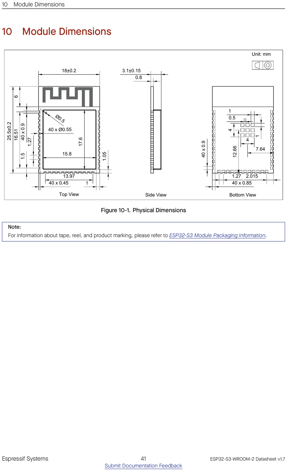
Physical
⚑ flag an error| Dimensions | 18 × 25.5 × 3.1 mm |
|---|---|
| Pin count | 41 |
| Temp range | -40 to 65 °C |
| Mounting | SMD castellated |
| Lifecycle | Active |
Security
⚑ flag an error| Secure boot | Yes |
|---|---|
| Flash encryption | Yes |
| Crypto | AES, SHA, RSA, HMAC, RNG |
| Digital signature | Yes |
| TRNG | Yes |
Ordering codes
⚑ flag an errorThe orderable part numbers and what each ships with — decoded from the suffix. Confirm against the latest datasheet before ordering.
| Part number | Flash | PSRAM | Temp |
|---|---|---|---|
ESP32-S3-WROOM-2-N32R16V | 32 MB · 1.8V | 16 MB (octal) | −40 to 85 °C |
ESP32-S3-WROOM-2-N16R8V | 16 MB · 1.8V | 8 MB (octal) | −40 to 85 °C |
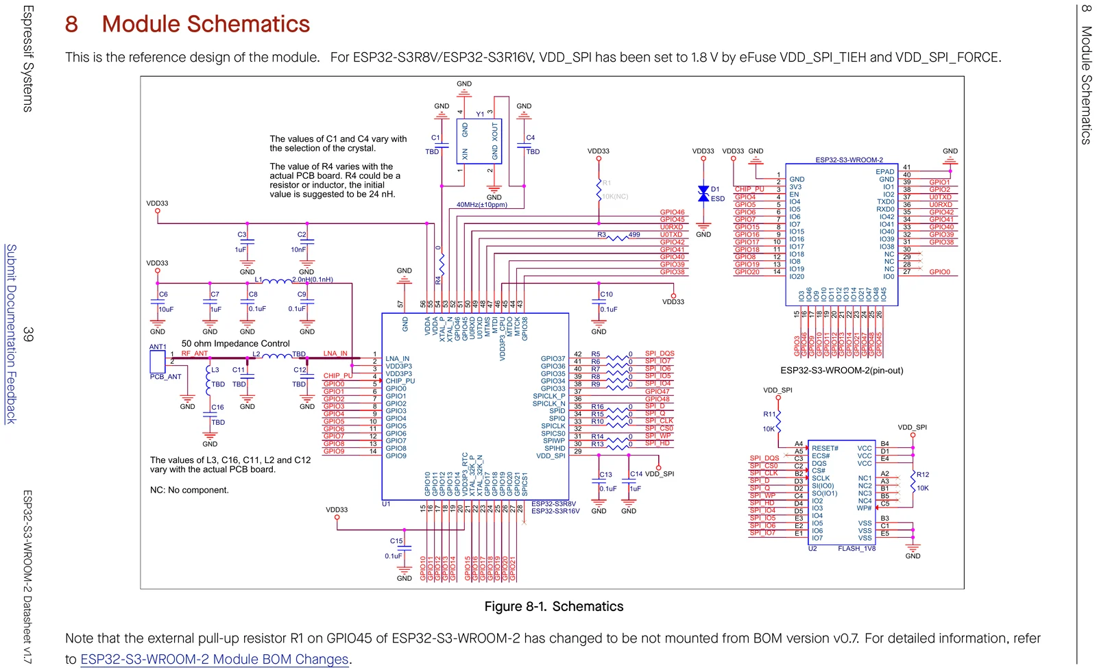
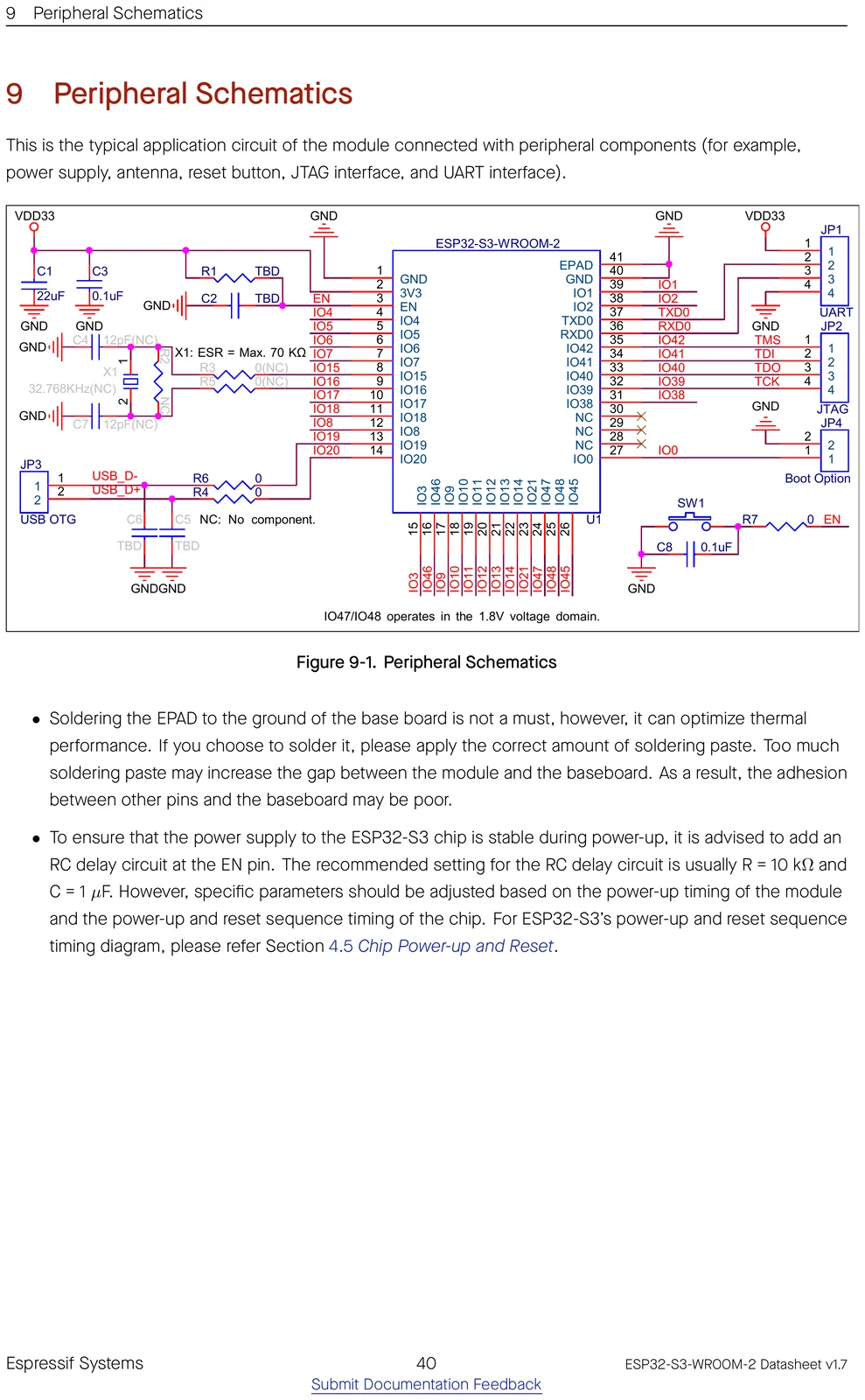
Schematics
Mechanical & CAD
Getting started
Frameworks: Arduino-ESP32 core — fully supported · ESP-IDF 4.4+ (Espressif's official SDK) · MicroPython · Matter.
ESP-IDF target: idf.py set-target esp32s3.
The SoC has native USB-OTG, so it can flash over USB and act as a USB device or host.
- Give the module a 3.3 V supply rated for at least 500 mA — RF transmit bursts pull well above the average current.
- EN is only weakly pulled high internally (~2 MΩ), which often isn’t reliable on its own. Add an external 100 kΩ pull-up, and for clean resets — especially with large bulk capacitance on the 3.3 V rail — use a reset-supervisor IC (e.g. MAX809) rather than just an RC network.
- Routing SPI (or most peripherals) through the GPIO matrix caps the SPI clock at 80 MHz; to run faster, use the dedicated IO_MUX pins.
Open-source projects using this module
Public GitHub projects whose KiCad design files reference the ESP32-S3-WROOM-2.
- shorepine/tulipcc ★ 918
The Tulip Creative Computer and AMYboard - portable Python synthesizers
- crgarcia12/electronics-homeassistant-lightscontroll ★ 28
- PyroVision-ThermalCam/Mainboard ★ 10
Mainboard for the PyroVision thermal camera.
- mikelawrence/esphome-indoor-multi-sensor-hardware ★ 9
ESPHome Indoor Multi-Sensor hardware. This design supports Radar/PIR Presence, Temperature, Humidity, Pressure, Light, CO2, CO, VOC, NOX and PM sensors. Add a speaker and microphone and you have the kitchen sink too! Click the link below to configure a new device.
- MS71/IndegoRover ★ 7
new MainBoard for Indego Lawn Mower
Frequently asked questions
Does the ESP32-S3-WROOM-2 have Wi-Fi and Bluetooth?
It provides 2.4 GHz Wi-Fi 4 and Bluetooth LE.
How much memory does the ESP32-S3-WROOM-2 have?
It comes with 16, 32 MB flash options, up to 16 MB of PSRAM, and the ESP32-S3 has 512 KB of on-chip SRAM.
How many GPIO pins does the ESP32-S3-WROOM-2 have?
The module breaks out 33 GPIO, with up to 20 12-bit ADC channels. See the full pinout above.
Can I use the ESP32-S3-WROOM-2 with the Arduino IDE?
Yes — install the Arduino-ESP32 core and pick an ESP32-S3-based board. You can also use ESP-IDF 4.4 or MicroPython.
How do I flash the ESP32-S3-WROOM-2?
The SoC has native USB-OTG, so it can flash over USB and act as a USB device or host.
Is the ESP32-S3-WROOM-2 5 V tolerant?
No. It runs at 3.0-3.6 V and its GPIO are not 5 V tolerant — level-shift any 5 V signals.
Can I use an external antenna with the ESP32-S3-WROOM-2?
Most Espressif modules are also offered in a "-U" / "-1U" variant that swaps the on-board PCB antenna for a U.FL/IPEX connector for an external antenna — otherwise identical. Check this part's datasheet for the exact variant name.
Further reading
- ESP32-S3-WROOM-2 Datasheet
- ESP32-S3 modules
- Certificates for ESP32-S3-WROOM-2
- Espressif Product Selector
- ESP32-S3 Datasheet
- ESP32-S3 Technical Reference Manual
- ESP32-S3 product page
- ESP-IDF Programming Guide
- Hardware Design Guidelines
- ESP Dev-Kits documentation
- Espressif KiCad libraries (symbols/footprints/3D)